-40%
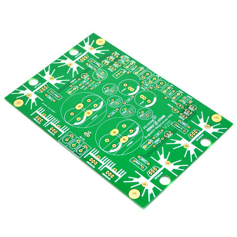
Hifi PSU Sigma22 series regulated servo linear power supply board/kit +/-DC Out
$ 4.75
- Description
- Size Guide
Description
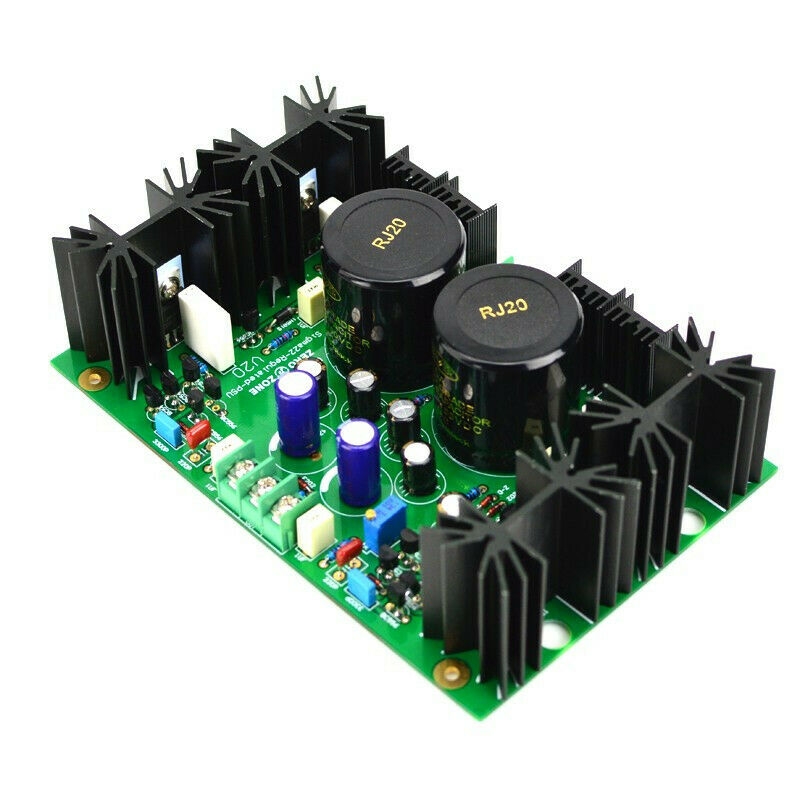
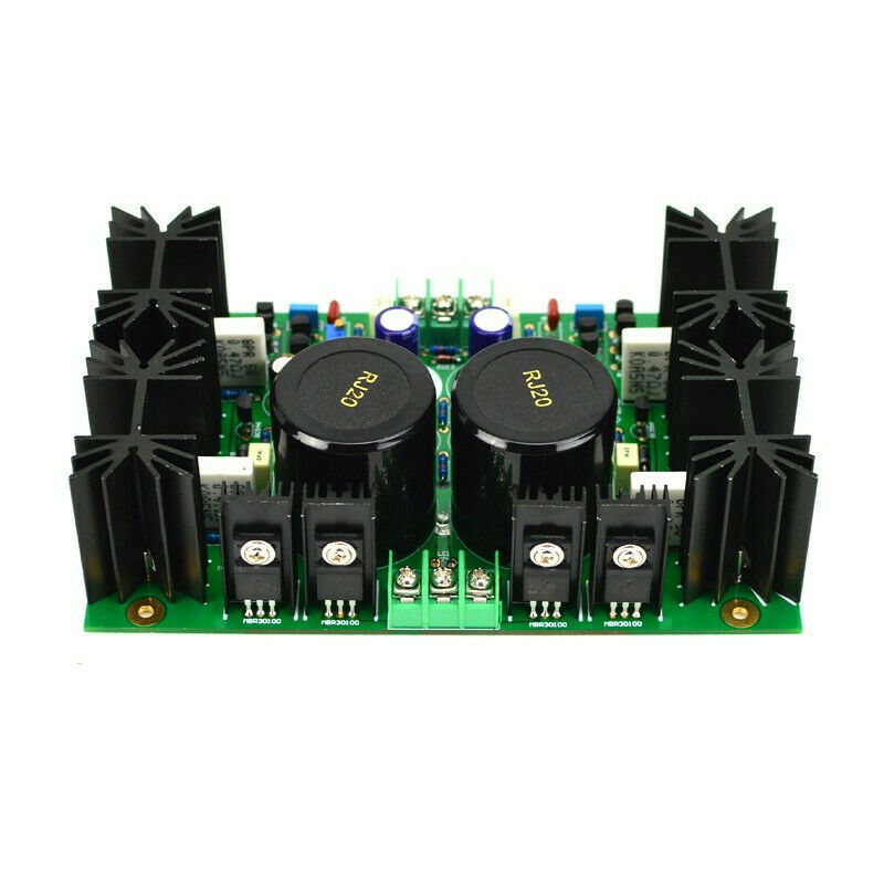
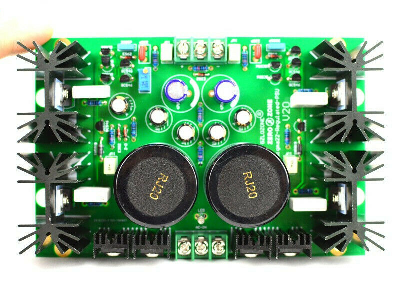
Details:PCB specification: 101mm*135mm*1.6mm, 1OZ copper, gold plated. New version V2.0 optimization point: 1:Use AMB Sigma22 V2.0 circuit diagram; 2:Use Schottky common cathode rectifier for smaller internal resistance and faster response 3:Compatible with many high-grade main capacitor's pin, [Description]: Sigma22 series voltage regulator circuit, single-digit UV level index, infinitely close to the battery level; maximum support for 30A current output; sense neutral, background super quiet, high resolution. By replacing the Zener tube, it can do 5V-36V dual power output, the maximum output is 30A, which is very suitable for medium and large amps and desktop power amplifiers, medium and high power rear stage. [Introduction]: Fully discrete component structure, single-stage series regulator design. No ic use, so that the entire design can control each control loop node to achieve the best performance parameters of the voltage regulator. The complementary voltage stabilizing structure, the negative voltage regulator part is the complementary mirror image of the positive voltage regulator part. Ultra-low noise, extremely high PSRR (power ripple rejection ratio). The low-pass filter's knee frequency is as low as 1.6 Hz to prevent diode switching noise from entering the error amplifier. This part also has a soft-start function. Effectively guarantees the output noise of the regulated power supply as low as μV. The high-current MOSFET ensures that the current output of the regulated power supply is sufficient and the current is as high as 30A. With high bandwidth, the Sigma22 is designed to have its own bandwidth and far beyond the audio bandwidth. The output impedance of sigma22 is far lower than the best low-ESR large-capacity electrolytic capacitors on the market. Due to the high bandwidth design of sigma22, sigma22 can easily cope with the ever-changing amplifier current requirements and ensure that the back-end amplifier can reach its full potential. (The output impedance is as low as μΩ, 1Ω = 1000mΩ = 1000000μΩ).
Voltage setting:
On the back of the PCB, has marked different Zener diode (base voltage) are selected for different output voltages. When Output is: +/- DC5-8V, Zener diode “Z-D” using 2V7 When Output is: +/- DC9-13V, Zener diode “Z-D” using 4V3 When Output is: +/- DC14-19V, Zener diode “Z-D” using 6V2 When Output is: +/- DC20-24V, Zener diode “Z-D” using 7V5 When Output is: +/- DC25-36V, Zener diode “Z-D” using 12V ( the DIY kit will include 2V7 4V3 6V2 7V5 12V 5pcs Zener diode )
Input voltage requirements:
Generally, the voltage difference after rectification of the input voltage should be 6-10V higher than the output voltage. [Calculation formula: input AC*1.414-output DC=6-10V] if the voltage difference is enough, and Do not consider heat dissipation. this board can output max currect about RMS 10A. peak 30A currect. but the standard heatsink can bear about 500mA currect load. if you need higher currect. please Strengthen the radiator.
About heat dissipation:
The heat sink as standard on the kit and the finished board can withstand nearly 2 watts of power consumption(each heatsink is about 1 watts power consumption). It can be predicted by PT=VI. When the heat is too large, it is recommended to use the chassis bottom plate for heat dissipation.
Note:
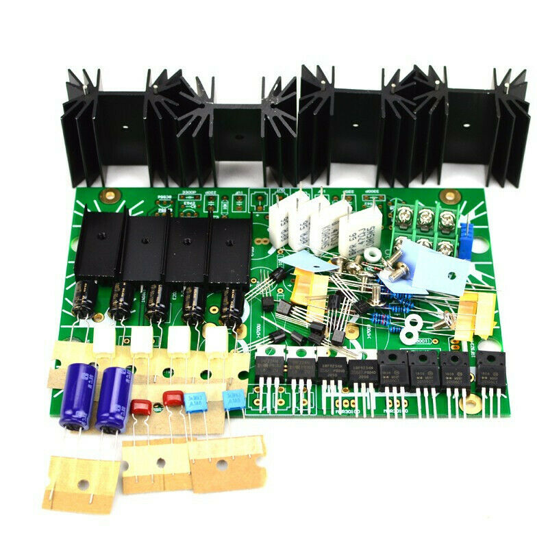
Bare pcb:just 1pcs pcb ,have no any parts Diy kit:all the parts need yourself to solder,included 2pcs NOVER 10000uf 50V main Capacitors Assembled board:have tested well,included 2pcs NOVER 10000uf 50V main Capacitors (
pls tell us what output voltage you need
)
